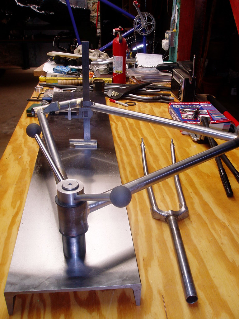
The fixture, once set up, is the part that holds all the mitered tubes.
A full front triangle is assembled, fluxed, and pinned.
I tack the bands on the head lugs, and the sometimes the points of the top and down tube lugs. (it depends on the fits).
I remove this ass'y and transfer it to the alignment table and use tube standards to keep the frame's own weight from skewing a reading.
I tack the seat tube/bb are in alignment.
I ensure the the head tube is "straight" using an M+L (Marchetti tool that extends a steering axis reading over a meter's length.
Then - i free braze all of this, because at this junction, the only errors
Are from my inattention rather than the tools. once the front triangle is brazed.
The flux washed, and the head tube reamed, i use the alignment table to see how close i came.
As jon wrote/suggested, the frames i keep are the ones that meet my alignment standards.
The ones that don't, get tossed.
I toss 3-4 a year on average.
e-RICHIE©™®
from Andy Stewart via this post:
From Doug Fattic via this post:
A fancy Italian-made alignment tool plus detail
Alex Wetmore has some sweet alignment tools he made in his basement, especially these dummy headset bits that hold a 7/8" cheater bar
--
From Cory Swartz


From Alex Meade:
Alex says:
Thanks to all who contributed.
Jamie Swan's piece in the Spring 2006 issue (Vol. 4, No. 3) of Vintage Bicycle Quarterly is required reading on the subject of frame alignment.
When I first got it I did very basic frame positioning for alignment. Simple "C" clamped the BB to the surface and used a Vernier caliper as a height gauge to measure up to the tubes. As time, imagination and $ allowed I've added a proper BB post, solid measuring tools, dial gauge and recently a fork vice/block for the surface. Each has made working with the surface easier and quicker. My time to build is hard to get these days so being able to take a pinned and tacked main triangle, align it and finish braze it quickly is nice. My BB post is a home designed thing. Steel, hardened and ground. Simple machine bolts and stepped washer are the clamp. Small machinePhotos of Andy's setup from my visit to his shop are on my Flickr
screw jacks act as the risers for tube support during bending. Various bars act as levers. Home made head tube cones for the alignment bar.
From Doug Fattic via this post:
One thing to remember if one is using V blocks on a flat surface to hold tubes is that the height difference between their flat bottom is not the same as the contact points of the V in the block. In other words, you can't raise the bottom of top tube (when it is a 1" tube) V block 1/16" (1/2 the diameter so the tube's centerlines agree) higher than a seat tube V block for a 1 1/8" tube. If memory serves me correctly it is .088" per 1/16" of diameter difference. I've got the formula somewhere if someone wants it.
This should be the height difference (.088") of the shim below a V block holding a 1" tube and a V block holding a 1 1/8" tube. Engineering students will already know this but my undergraduate and graduate studies were in the behavioral sciences (psychology, counseling) so it had to be explained to me.
--
Alex Wetmore has some sweet alignment tools he made in his basement, especially these dummy headset bits that hold a 7/8" cheater bar
--
From Cory Swartz
I've made a few different BB posts recently, for different things. 68mm was the intended shell, but 70, 73, anything w/ that same OD/ID would work.
Tandems, EBB, BMX would require some additional pcs that I haven't worked out just yet.
Used 2" round stock, 1018 CRS. Maybe not the fanciest but it is quite economic and very readily available.
I made the diameter to fit inside the bb 1.325" if I remember correctly, nice and snug but not too tight to bugger the threads.
Basically just split the 68mm width in half w/ about an extra .030" or so clearance between the two pcs in case you come across a shell that's a little undersized in width. That's how I got that length, and the bottom surface of the shell to the top of the plate at 100mm seems to be pretty popular.
I think I made the top "cap"(?) @ 1" thick, 3/4" maybe, I forget....
Tapped a 3/8" hole in the center of the bottom and clearance and c/bore for the 3/8 SHCS in the top to hold 'em together.
The bottom of the bottom would be tapped whatever you want. 5/8 or 3/4 or even 1" would be my pick if the bolt holding it to the table is really long.
The one I did for Owen [Lloyd] a while back I think was 3/8, but then he had some other mounting considerations involved.

This is the one I made for Owen [Lloyd], so he could mount to existing inserts in his surface table.

The other(taken apart) is one I made a year or so ago as a "first shot" playing w/ stuff, but you can get the idea...--
From Alex Meade:
Alex says:
Pretty basic. Hunk of channel iron, which I was fortunate enough to be able to talk a friend into surface grinding for me. Post started out as 2" diam A2 tool steel (got it cheap on eBay), turned threads on both ends, a big nut holds it to the bottom of the channel iron. If I had it to do over again, I'd have turned the post to be a nice tight slip fit for Campy BB facing tool inserts. As it stands now, I usually have to loosen/tighten the top nut after a good tweak to the frame. One day maybe I'll make some inserts for it. Once I finished the post, I heat treated it to Rc 62 so the shoulder doesn't wear with repeated contact with BB shells. So far so good on that score. Top nut is aluminum.--
Thanks to all who contributed.
Jamie Swan's piece in the Spring 2006 issue (Vol. 4, No. 3) of Vintage Bicycle Quarterly is required reading on the subject of frame alignment.


No comments:
Post a Comment