just got out of another intro to metal sculpture class.
i discussed with the teacher how to make the rake spacer block, which i've made once but i think i'll re-do. this time i'm going to precisely control the alignment of the two holes drilled in it, which secure the angle iron bits to its top and the whole assembly to the backboard.
i was thinking about the way this design works last night. it breaks down the directions in which motion needs to be controlled and controls each one with a different mechanism.
1. the dropouts need to be held apart 100 mm
2. they must be suspended above the backboard top by the rake amount + the steerer's radius
3. they must be aligned perpendicular to the steerer axis
4. they must be secured a specific distance from the crown
the arrangement is made somewhat clearer by looking at the Talbot jig drawings, upon which all this is based.
anyways, by replacing talbot's pine axle block i'm able to independently control each variable. the pine block controls 2 and 3 with one function: the hole drilled through it. if the hole gets drilled at all off, everything is outta whack.
so i seperated the two functions into two parts: a spacer block to control #2, and two angle iron bits on top to control #3. they each depend on the other, but now i have more control over the dummy axle's position.
i suppose this is all part of rudimentary jig/fixture design, but i've had no schooling so i'm playing it by ear.
design as jigged
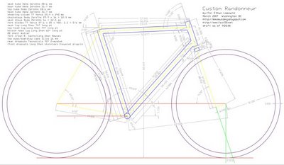
this is a .pdf of the AutoCAD drawing i finished last night. it's still kinda sloppy, and this is with all the dimensions and labels turned on so it's detailed but crowded. Little Fish's drawings provided lots of inspiration.
i tried to braze yesterday without much guidance, and thus without much success. i was using a PurOx #4 tip, which looking back was probably too big. cleaning everything went pretty well, although i learned that i need thick rubber gloves to handle toilet bowl cleaner (Lysol disinfectant, 9.5% HCl). the medical gloves i had on fell apart after cleaning a couple parts. also i was doing a mock head tube-top tube join, which seemed to heat up way too fast to get any good results.
too busy to blog...almost
so the move-in is mostly complete, after much laborious disassembly and reassembly of Swedish furniture. i had to put the bike mostly on hold for a week or so to get everything set up.
today i talked to one of my teachers (actually for a furniture class) about teaching me to braze next week. we went over all the stuff we'll need, and it sounded like his knowledge generally jives with what i know from my research. my teacher is Andrew Christenberry, a cool guy, a great furniture maker/sculptor, and son of William Christenberry (the DC-based photographer/artist).
then i got to work setting up a practice joint to silver braze. cut a ~4" length of 31.7 mm diameter .035" 4130 tubing (gotta conserve it, i lost my head tube, so i plan to substitute 4130), cut a longer length of 1" diameter, roughed out the miter by scribing inside the lug and bench grinding almost to the line, got it pretty close with emery wrapped around the 31.7 tube. next i went to work reaming out the lug a little, using a mini air-powered die grinder and grinding stones from McMaster--3/4" and 1" diameters. the 1" socket was pretty quick, but i think the lug is a little torqued in the 31.7 socket because i had to grind like hell just to get it to fit OK, while the smaller socket took just a few minutes.
i degreased and deburred all these parts using denatured alcohol. another of the sculpture dept. faculty said DnA is good for degreasing and better for the environment than acetone, so i plan to pick some up for pre-brazing clean-up. the archives aren't especially informative on this application of DnA, and there was a frameforum thread on brazing clean-up i can't find right now. i'll try it and see how it works.
the AutoCAD plot is almost done. i'll plot a final tomorrow night, mount it to the backboard, then get to work on finishing the main triangle jig.
i made the maple rake spacing block i alluded to in an earlier post. this took some doing, with many failed attempts that were a little too out of square. next up for the fork jig are the angle iron pieces that will hold the dummy axle and sit on top of the spacer block.
lastly, a short rant on IKEA furniture: it's decent, it's cheap, but their bolts are steel and that's dumb. brass would hold together far better far longer at (i imagine) a small price increase. this weekend i took apart a loft bed that required a lot of cursing and hammering. the IKEA guy who put it together must have been in a hurry, because the bolt heads were stripped something awful.
tats
http://cyclingtattoogallery.blogspot.com/
be sure to see Sacha White's contribution: his wrists inked with the Vanilla headbadge design
i'd link directly but it's a slick Flash gallery. there's also a badass Joker leg tat.
i'm moving to a new apartment in DC this weekend, so it'll be a bit before i'm on-line there.
also the school shops are closed this weekend, and i have a paper due monday, so the bike has to move to the back of the bus for a little while.
the good news is that the front triangle jig is coming along nicely. last week i finished cutting and drilling all the angle iron that will act as clamping blocks, so this week the big job is to clamp those pieces to the backboard, drill holes into it through the existing ones, then run bolts through and tighten it all down. the tricky part i forsee is lining the angle iron up and clamping it down in perfect alignment with the lines on the drawing. once this step is complete, the front triangle dimensions are set in stone, so i may wait until i finish the AutoCAD drawing i'm doing.
new fork jig
after reading Chauncey's comment (see 2 posts down) and drawing up some basic plans, i've decided i'll re-do the fork jig. the new one will use 2 short lengths of angle iron to hold the dummy axle. the angle iron will rest on top of a maple spacing block, equal in height to the desired rake minus a set amount. thus the jig will be re-usable for different rake amounts by making a new spacer block. the maple will come from some scrap from stairs that my grandfather is having made. all this is kinda hard to describe with just words, but i'll be working on it over the next week and post photos after it's done. the first step will be to remove the 2x4 that's glued to the backboard so i can re-use it, first with a table saw and then with a planer to flatten it again.
fabrication/bending link
http://www.thefabricator.com/TubePipeFabrication/TubePipeFabrication_Article.cfm?ID=721
photos of today's work

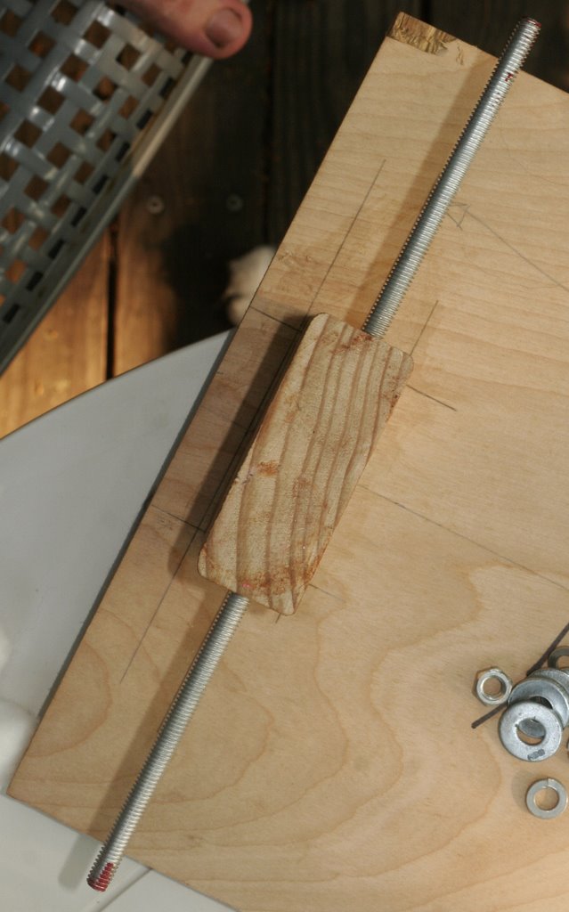

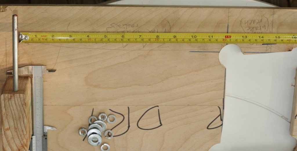
first up the fork jig. it's at least within a mm of square, about as best as i could manage with a drill press and miter saw. the axle block is part of a 2x4 that was in the scrap pile. it's just glued to the backboard now, i've drilled pilot holes into it from the back, next is to drive wood screws.
the bit must have walked or something because after measuring the axle's actual height and subtracting half the fork blade's height, it turns out i've only got about 64.5 mm rake, and actually it's maybe a half mm more on the right side. either i'll live with it or i'll try the Paterek fork cold un-twisting method: insert a long screwdriver between the blades and pry them in the necessary direction.
i made the opening for access to the the crown by drilling out the corners with a 1 1/2" spade bit in an electric drill, then connected the holes with a jigsaw. looks like i could have made it even smaller and still left plenty of room for drilling and pinning.
the next addition will likely be a section of angle iron at the left side, to which i'll clamp the steerer for pinning. i'll probably start on that tomorrow. our shop has a horizontal band saw for cutting metal, with a hydraulic mechanism to control how fast it cuts--sounds perfect for 1/8" thick angle iron.
now to the molten metal...wait, make that later...
my first time
i melted steel just a few minutes ago. i just wanted to start getting a feel for controlling heat, so i made a puddle of molten steel and pushed it around, first in straight lines, then into a rather pathetic-looking design. but, damn it's cool. and melting steel seemed at least a little analagous to melting brazing rod--it was hard to learn to control how molten it was. i went from just willy-nilly heating to having at least a little control in just the few minutes i was at it.
more progress...
today i drilled the axle block for the fork jig and glued it to the fork jig backboard. see the Talbot drawings to know what i mean. the disadvantage to the wooden fork jig method is that it's completely one-off: the rake is going to be near impossible to change now that the block is glued down. the advantage is the only parts i paid for are some angle iron to secure the steerer ($20 for 6 ft. at Home Depot, probably enough for the main jig as well) and some 5/16" threaded rod to simulate an axle ($2?). i did some calculations based on measurements made with the calipers to figure out where to drill the axle hole: it's set above the backboard by (65.5 mm rake) + (half of fork blade diameter at top, long ways) = about 78 mm IIRC. based on a video i saw on that Virtual Machine Shop site, i used the calipers to scribe the lines. the hole came out pretty square, maybe 1 mm off, so when i glued it down i made the axle parallel to the line i had drawn previously, rather than line up the axle block. more later, plus photos.
front end dimensions
in mm; made with Chinese 6" Vernier calipers from Enco
Long Shen 60° oversized long point bottom head lug
lower intercept (distance along interior surface from headset face to bottom of DT socket): 5
Sachs Newvex crown
after filing to remove casting texture
max. clearance between stiffener supports: 44.1
brake hole center to crown bottom: 11.1
crown height: 18.5
Long Shen stainless double-eyelet plug-in front dropout (left measured)
as cast
*OD of plug: 12.8
OD of lip: 14.0
lip to lower eyelet center: 10.7
*lip to closest edge of axle slot: 17.9
*lip to axle center: ~23.5
eyelet c-c: 27.2
True Temper VERUSFB1 blades
as drawn
top OD, long ways: 27.8
top OD, short ways: 20
bottom OD: 12.5
bottom ID: 10.6
top to start of taper: ~110
respirators
i've spent a few hours researching respirators lately. yeah, i'm a dork.
at first glance at 3M's respirator and accessory options, i had no idea what i needed, but after looking over their literature i was able to figure it out and get (i think) exactly what i need.
most helpful were the following .pdfs from 3M:
2006 Respirator Product Selection Guide
Half and Full Facepiece Respirators Brochure
Respirator Cartridge and Filter Selection
i ended up buying everything through Cooper Safety, simply because they had the best prices and had everything in stock.
i wanted a system that would filter out all the contaminants i plan to encounter: hydrochloric acid (HCl, in Sno-Bol, for brazing cean-up); acetone (for removing oils prior to HCl), brazing fumes, and particulates generated by grinding. i found out an Acid Gas cartridge is needed for HCl gases, an Organic Vapor for acetone, and a particulate filter is for the other two. there's about six different kinds of particulate filters; the choice is made based on whether or not the particulates are attached to oil molecules (N if not, R if sometimes, and P if yes) and what degree of "filter efficiency" is needed (95=95%, up to 100=99.97% or so). i don't really know for sure what i need in these departments. my metal teacher said N95 is fine for grinding, so i got one of those and a P100 for anything really serious.
to protect against all of these you need the following:
a mask, which straps to your face, covering nose and mouth. i got a 6000, seems adequate.
a pair of cartridges, one of which couples to each side of the mask. there's an array of them available to protect against almost anything. i got an OV/AG: Organic Vapors and Acid Gas.
to add particulate protection, there's a couple options: you can add a pre-filter and retaining ring to the outside of the cartridge, or add a filter adaptor to allow fitting circular filters to the rectangular cartridge (which i opted for, mostly because that's what they had).
i'm still not sure if the filter can be used by itself, which i'd think would be good if the cartridge causes some breathing resistance.
new ad
you may have already noticed the big red square over on the right there.
don't be alarmed; no one's selling out here.
the red square replaces the far lamer Google AdWords box i had, which was fine but often had irrelevant ads.
b minus is run by a good guy and the shirts are cool. the money i get from having the ad helps keep this project going, and that's good for me and you.
so order a shirt or two!
first metal class
started my intro to metal sculpture class last night. great instructor, talked for about 3 hours straight. we covered all the safety stuff, which took most of the time, and then went over how to use an oxy-acetylene rig. the class will mostly focus on MIG welding, but i think i'll be able to get enough brazing practice. plus learning to MIG can't hurt.
this is just meant to be FYI. i can imagine it being useful if one wanted to build their own brazing rig, or even just to better understand how this mysterious contraption works.
i'll start with a breakdown of the parts involved in an oxy-fuel rig:
tanks: one for oxy, one for fuel. each tank has a valve directly attached to it, acting as the main on-off.
regulators: each tank has one attached directly downstream of the tank valve. generally oxy regulator dials are green and fuel are red. controls how much gas pressure flows through the lines. clockwise turning of the screw increases pressure; when screw feels loose, regulator is off.
lines/hoses: same color-coding as regulator dials. connections for fuel are reverse-threaded to avoid confusion.
flashback arrestors: one for each line, located downstream of it right where it attaches to the torch. prevents flashback, which is really bad but that's all i know about it. make sure they're tight.
mixing handle/torch/torch handle: this is the big brass cylinder that one holds while welding/cutting/heating/brazing. gases from the lines mix here. has a valve for each gas to control how much is let in.
tip: secured to the handle by means of a collar. interchangeable for welding different thicknesses of metal and different purposes.
safety check
1. make sure tanks are chained up.
2. make sure regulator screws are loose (off).
3. make sure torch knobs are tight (off).
start-up
open acetylene tank valve handle half turn
crack oxy tank valve handle slowly, then open fully
open acetylene torch valve about half turn
open acetylene regulator to recommended psi (refer to chart; based on tip size)
close acetylene torch valve
open oxygen torch valve about half turn
open oxygen regulator to recommended psi (refer to chart; based on tip size; add 1-2 psi usually)
close oxygen torch handle valve
the reason for all this opening and closing is to set the regulator when the lines are open at the torch end, because the recommended pressures are for flow pressure (as opposed to static pressure, when the lines are closed and the gas is contained).
lighting the torch
put on welding gloves and put goggles on head (not over eyes yet).
open acetylene torch valve quarter turn
if there's a gap between tip and flame, close acetylene valve until flame smokes, then open up; gap should disappear.
put goggles over eyes
crack oxygen torch valve slowly with thumb and palm, then open up with fingertips to adjust flame. neutral is best for welding mild steel, but i think it's different for brazing. neutral means the outer blue cone is the same size as the inner blue cone.
turning torch off
close oxygen torch valve
close acetylene torch valve
rub tip on glove or pants or whatever to remove any acetylene buildup
shutting down
turn off acetylene tank valve--tight
turn off oxygen tank valve--tight
bleed each line, acetylene 1st, by opening respective torch valve half turn until regulator reads 0, then close torch valve.
loosen/close both regulator screws (about 2 turns)
remove torch tip
loosely wind hoses around cart handles
does this jive with what others do?
and another thing
http://jjjtrain.kanabco.com/vms/index.html
this is one of those things, like Frameforum and WikiPedia and imdb, that make the internet so flippin' sweet.
i have access to a milling machine this fall, but apparently almost nobody at my school knows how to use it. but after learning a bit from this site and some practice and guidance i figure i oughtta be able to make some cool stuff.
of particular interest to readers:
heat treating
metallurgy
boring with a vertical mill (looks like a good way to make a head tube sleeve from 4130 tubing, as previously described in an email to the FBs list)
an exhaustive glossary
cool background reading:
fundamentals of measurement and related lingo
also a sweet forum/message board
this is an awesome t-shirt
http://www.universalcycles.com/shopping/product_details.php?id=12890&category=
thanks for comments to the previous post, people.
thanks for comments to the previous post, people.
filing, drilling
started sharpening the points of the lugs (thanks dave bohm) and drilling holes for pins tonight. learned a couple lessons.
• here's background on pinning by Fred Parr. i ordered one of his pinning kits: a bag of nails and two of each drill bit needed.
• tonight i was drilling the pilot holes in a few real and practice lugs. the procedure is prick punch, then center punch, then drill with lots of oil. got the punches at Home Depot; the oil is just 3-in-1 oil. learned about punches from Paterek. they didn't make as big an indentation as i expected.
• i discovered stamped lugs are pretty fragile when i tried to prick punch one rather hard. the opening deformed a little...hopefully i'll be able to re-form it so a practice tube will fit. i bought three stamped lugs from Tom Palermo the other day--really lovely to begin with, great shorelines and windows. i've been practicing lug cutting and now drilling on them.
• i'm using tapered wooden dowels to hold the lugs for filing, so i used to dowel to hold the lug, clamped the dowel horizontally with the right spot facing up, and drilled down through the lug into the dowel. the 8" half round was perfect for cleaning up the holes.
• before calling it a night, i tested out the whole pinning setup. i used a short section i had trimmed from the end of the down tube to get it roughly the right length before mitering. drilled the pilot hole in the lug, drilled through that hole into the tube, deburred both holes, and tapped a pin in. the assembly felt really very strong, although looking back at it i realize the lug hadn't yet been properly reamed out for a good clearance with the tube. 'sposed to be at least a slip fit, but it was still kinda tough to slip that tube in there.
• i recall Fred mentioning something about pinning each tube in at least three places to keep it secure in three dimensions. this may be kinda tricky with the type of jig i'm using, which obviously doesn't allow access to all of the frame at once. i'm working on this one.
Subscribe to:
Comments (Atom)

